Book Overview: Building Arduino Projects for the Internet of Things
My new book Building Arduino Projects for the Internet of Things was released earlier today. It is available for purchase on all major stores (Buy Now). This post provides an overview of the book.
What This Book Covers
This book is based on my personal experience of getting started with IoT. It is divided into two logical sections. The first one teaches the basics of building IoT applications and the second section follows a project-based approach. At the end of each chapter, you will have a working prototype of an IoT application.
Part 1: Building Blocks
Chapters 1-3 cover the building blocks of IoT:
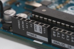
- Chapter 1, “Arduino Basics,” introduces the Arduino prototyping platform, which is used throughout the book.
- Chapter 2, “Internet Connectivity,” discusses the different options available for connecting things to the Internet.
- Chapter 3, “Communication Protocols,” teaches you which communication protocols are and which ones are available for IoT.
Part 2: Prototypes
Chapters 4-12 use the information covered in Part 1 to build prototypes of IoT applications.
- Chapter 4, “Complex Flows: Node-RED,” introduces Node-RED, which is a visual designer that helps reduce the amount of code required for IoT applications.
- Chapter 5, “IoT Patterns: Realtime Clients,” talks about components required for building IoT applications that provide data to users in real time and shows you how to build an intrusion detection system as an example.
- Chapter 6, “IoT Patterns: Remote Control,” discusses components of IoT applications that can remotely control things, such as a lighting control system.
- Chapter 7, “IoT Patterns: On-Demand Clients,” shows you different components involved in building an on-demand IoT application. You’ll build a smarter parking system in this chapter.
- Chapter 8, “IoT Patterns: Web Apps,” teaches you scenarios where web clients are preferred and uses a temperature monitoring system as an example.
- Chapter 9, “IoT Patterns: Location-Aware Devices,” discusses the importance of location-aware devices. You’ll develop a livestock tracking system as an example.
- Chapter 10, “IoT Patterns: Machine to Human,” talks about scenarios where a human response is needed; you’ll build a waste management system as an example.
- Chapter 11, “IoT Patterns: Machine to Machine,” discusses a pattern of IoT that is going to be very popular as things get smarter. The example is an energy conservation system.
- Chapter 12, “IoT Platforms,” wraps up the book by introducing you to IoT platforms that help expedite entry into IoT. The example in this chapter builds a soil moisture control system.
Download Source Code
Download code directly from Apress website or the GitHub repository.

IoT Sensors - #8: Capacitive Touch Sensor
This article is the eighth in a series on Internet of Things (IoT) sensors. It teaches you about various sensors available and how to read data from them.
Hardware
- Arduino Uno
- Capacitive Touch Sensor
- Jumper Cables

Software
Circuit
Step 1: Make sure your Arduino is not connected to a power source.
Step 2: Using jumper cables connect power (VNC) and ground (GND) ports on Arduino to power (+) and ground (-) ports on the breadboard.
Tip: It is a good practice to use red jumper cable for power (+ / VNC) and black jumper cable for ground (- / GND).
Step 3: Now that your breadboard has a power source, using jumper cables connect power (+) and ground (-) ports of your breadboard to power and ground ports of the Capacitive Touch sensor.
Step 4: To read capacitive touch sensor values, you will need to connect a jumper cable from signal (SIG) port of Capacitive Touch sensor to D3 (Digital) port of your Arduino.
Your circuit is now complete and it should look similar to figures below.

Arduino Code
Next, you are going to write Arduino code that will read sensor data. Start your Arduino IDE and either type the code provided below or download it from GitHub. All the code goes into a single source file (*.ino) but in order to make it easy to understand and reuse, it has been divided into 3 sections.
- External Libraries: includes all libraries required to run the program
- Sensor Setup: code for reading sensor data
- Standard Arduino Functions: implementation of standard Arduino functions setup() and loop()
[code lang="js"]
/***************************************************************************
* External Libraries
**************************************************************************/
#include <SPI.h>
/*****************************************************************************
* Sensor Setup - Variables & Functions
****************************************************************************/
int CAPACITIVE_SENSOR_PIN = 3;
int capacitiveSensorValue = 0;
void readSensorData()
{
//Read Sensor Value
capacitiveSensorValue = digitalRead(CAPACITIVE_SENSOR_PIN);
//Display Readings
Serial.print("[INFO] Capacitive Touch Sensor Reading: ");
Serial.println(capacitiveSensorValue);
}
/***************************************************************************
* Standard Arduino Functions - setup(), loop()
**************************************************************************/
void setup()
{
pinMode(CAPACITIVE_SENSOR_PIN, INPUT);
// Initialize serial port
Serial.begin(9600);
}
void loop()
{
readSensorData();
delay(1000);
}
[/code]
Final Product
Make sure your Arduino is powered on and code from above has been deployed. As soon as you touch the sensor value of 1 will displayed.

IoT Sensors - #7: Flame Intensity
This article is the seventh in a series on Internet of Things (IoT) sensors. It teaches you about various sensors available and how to read data from them.
Hardware
- Arduino Uno
- Flame Intensity Sensor
- Jumper Cables

Software
Circuit
Step 1: Make sure your Arduino is not connected to a power source.
Step 2: Using jumper cables connect power (VNC) and ground (GND) ports on Arduino to power (+) and ground (-) ports on the breadboard.
Tip: It is a good practice to use red jumper cable for power (+ / VNC) and black jumper cable for ground (- / GND).
Step 3: Now that your breadboard has a power source, using jumper cables connect power (+) and ground (-) ports of your breadboard to power and ground ports of the Flame Intensity sensor.
Step 4: To read flame intensity values, you will need to connect a jumper cable from the signal (OUT) port of Flame Intensity sensor to A0 (Analog) port of your Arduino.
Your circuit is now complete.
Arduino Code
Next, you are going to write Arduino code that will read sensor data. Start your Arduino IDE and either type the code provided below or download it from GitHub. All the code goes into a single source file (*.ino) but in order to make it easy to understand and reuse, it has been divided into 3 sections.
- External Libraries: includes all libraries required to run the program
- Sensor Setup: code for reading sensor data
- Standard Arduino Functions: implementation of standard Arduino functions setup() and loop()
[code lang="js"]
/***************************************************************************
* External Libraries
**************************************************************************/
#include <SPI.h>
/*****************************************************************************
* Sensor Setup - Variables & Functions
****************************************************************************/
int FLAME_SENSOR_PIN = A0;
float flameSensorValue = 0.0;
void readSensorData()
{
//Read Mositure Sensor Value
flameSensorValue = analogRead(FLAME_SENSOR_PIN);
//Display Readings
Serial.print("[INFO] Flame Sensor Reading: ");
Serial.println(flameSensorValue);
}
/***************************************************************************
* Standard Arduino Functions - setup(), loop()
**************************************************************************/
void setup()
{
// Initialize serial port
Serial.begin(9600);
}
void loop()
{
readSensorData();
delay(1000);
}
[/code]
Final Product
Note: For testing purposes make sure you are in an open space away from items that can catch fire. This post used a flame lighter for testing.
Make sure your Arduino is powered on and code from above has been deployed. As soon as your sensor gets close to a flame, the readings will start going down.

IoT Sensors - #6: Location Detection (GPS)
This article is the sixth in a series on Internet of Things (IoT) sensors. It teaches you about various sensors available and how to read data from them.
Hardware
- Arduino Uno
- Location Detection Sensor (GPS)
- Jumper Cables

Software
Circuit
Step 1: Make sure your Arduino is not connected to a power source.
Step 2: Using jumper cables connect power (VNC) and ground (GND) ports on Arduino to power (+) and ground (-) ports on the breadboard.
Tip: It is a good practice to use red jumper cable for power (+ / VNC) and black jumper cable for ground (- / GND).
Step 3: Now that your breadboard has a power source, using jumper cables connect power (+) and ground (-) ports of your breadboard to power and ground ports of the GPS.
Step 4: To read coordinates from GPS, you will need to connect a jumper cable from RX (Receive) port of GPS to D3 (Digital) port of Arduino.
Step 5: Similar to step 4, you will also need to connect a jumper cable from TX (Transmit) port of GPS to D2 (Digital) port of Arduino.
Note: Depending on your GPS module you might need to add transistors in the circuit as well, please check specifications of your GPS module.
Your circuit is now complete and it should look similar to figures below.

Arduino Code
Next, you are going to write Arduino code that will read sensor data. Start your Arduino IDE and either type the code provided below or download it from GitHub. All the code goes into a single source file (*.ino) but in order to make it easy to understand and reuse, it has been divided into 3 sections.
- External Libraries: includes all libraries required to run the program
-
<TinyGPS.h> - https://github.com/mikalhart/TinyGPS/releases/tag/v13
-
- Sensor Setup: code for reading sensor data
- Standard Arduino Functions: implementation of standard Arduino functions setup() and loop()
[code lang="js"]
/***************************************************************************
* External Libraries
**************************************************************************/
#include <SPI.h>
#include <TinyGPS.h>
#include <SoftwareSerial.h>
/*****************************************************************************
* Sensor Setup - Variables & Functions
****************************************************************************/
TinyGPS gps;
SoftwareSerial ss(2, 3); // GPS TX = Arduino D2, GPS RX = Arduino D3
static void smartdelay(unsigned long ms)
{
unsigned long start = millis();
do
{
while (ss.available())
gps.encode(ss.read());
} while (millis() - start < ms);
}
void getGPSCoordinates()
{
float latitude;
float longitude;
unsigned long age = 0;
gps.f_get_position(&latitude, &longitude, &age);
// Transmit sensor data
if(latitude != TinyGPS::GPS_INVALID_F_ANGLE &&
longitude != TinyGPS::GPS_INVALID_F_ANGLE)
{
Serial.print("[INFO] Latitude: " + String(latitude));
Serial.println(", Longitude: " + String(longitude));
}
else
{
Serial.println("[INFO] Searching for Satellite");
}
smartdelay(10000);
}
/***************************************************************************
* Standard Arduino Functions - setup(), loop()
**************************************************************************/
void setup()
{
// Initialize serial port
Serial.begin(115200);
// Initialize serial port for GPS data
ss.begin(9600);
}
void loop()
{
// Get GPS Coordinates
getGPSCoordinates();
}
[/code]
Final Product
Make sure your Arduino is powered on and code from above has been deployed. As soon as the code has been deployed, open serial monitor.

IoT Sensors - #5: Proximity Detection
This article is the fifth in a series on Internet of Things (IoT) sensors. It teaches you about various sensors available and how to read data from them.
Hardware
- Arduino Uno
- Proximity Detection Sensor
- Jumper Cables

Software
Circuit
Step 1: Make sure your Arduino is not connected to a power source.
Step 2: Using jumper cables connect power (VNC) and ground (GND) ports on Arduino to power (+) and ground (-) ports on the breadboard.
Tip: It is a good practice to use red jumper cable for power (+ / VNC) and black jumper cable for ground (- / GND).
Step 3: Now that your breadboard has a power source, using jumper cables connect power (+) and ground (-) ports of your breadboard to power and ground ports of the Proximity Detection sensor.
Step 4: To trigger a burst connect a jumper cable from TRIG pin of the sensor to D2 (Digital) port of Arduino.
Step 5: To read echo connect a jumper cable from ECHO pin of the sensor to D3 (Digital) port of Arduino.
Your circuit is now complete and it should look similar to figures below.

Arduino Code
Next, you are going to write Arduino code that will read sensor data. Start your Arduino IDE and either type the code provided below or download it from GitHub. All the code goes into a single source file (*.ino) but in order to make it easy to understand and reuse, it has been divided into 3 sections.
- External Libraries: includes all libraries required to run the program
- Sensor Setup: code for reading sensor data
- Standard Arduino Functions: implementation of standard Arduino functions setup() and loop()
[code lang="js"]
/***************************************************************************
* External Libraries
**************************************************************************/
#include <SPI.h>
/*****************************************************************************
* Sensor Setup - Variables & Functions
****************************************************************************/
int calibrationTime = 30;
#define TRIGPIN 2 // Pin to send trigger pulse
#define ECHOPIN 3 // Pin to receive echo pulse
void calibrateSensor()
{
//Give sensor some time to calibrate
Serial.println("[INFO] Calibrating Sensor ");
for(int i = 0; i < calibrationTime; i++)
{
Serial.print(".");
delay(1000);
}
Serial.println("");
Serial.println("[INFO] Calibration Complete");
Serial.println("[INFO] Sensor Active");
delay(50);
}
void readSensorData()
{
// Generating a burst to check for objects
digitalWrite(TRIGPIN, LOW);
delayMicroseconds(10);
digitalWrite(TRIGPIN, HIGH);
delayMicroseconds(10);
digitalWrite(TRIGPIN, LOW);
// Distance Calculation
float distance = pulseIn(ECHOPIN, HIGH);
Serial.println("[INFO] Object Distance: " + String(distance));
}
/***************************************************************************
* Standard Arduino Functions - setup(), loop()
**************************************************************************/
void setup()
{
// Initialize serial port
Serial.begin(9600);
// Set pin mode
pinMode(ECHOPIN, INPUT);
pinMode(TRIGPIN, OUTPUT);
// Calibrate sensor
calibrateSensor();
}
void loop()
{
// Read sensor data
readSensorData();
// Delay
delay(5000);
}
[/code]
Final Product
Make sure your Arduino is powered on and code from above has been deployed. As soon as the code has been deployed, open serial monitor.

IoT Sensors - #4: Motion Detection
This article is the fourth in a series on Internet of Things (IoT) sensors. It teaches you about various sensors available and how to read data from them.
Hardware
- Arduino Uno
- Motion Detection Sensor
- Jumper Cables

Software
Circuit
Step 1: Make sure your Arduino is not connected to a power source.
Step 2: Using jumper cables connect power (VNC) and ground (GND) ports on Arduino to power (+) and ground (-) ports on the breadboard.
Tip: It is a good practice to use red jumper cable for power (+ / VNC) and black jumper cable for ground (- / GND).
Step 3: Now that your breadboard has a power source, using jumper cables connect power (+) and ground (-) ports of your breadboard to power and ground ports of the Motion Detection sensor.
Step 4: To read motion sensor values, you will need to connect a jumper cable from signal (middle) port of Motion Detection sensor to D3 (Digital) port of your Arduino.
Your circuit is now complete and it should look similar to figures below.

Arduino Code
Next, you are going to write Arduino code that will read sensor data. Start your Arduino IDE and either type the code provided below or download it from GitHub. All the code goes into a single source file (*.ino) but in order to make it easy to understand and reuse, it has been divided into 3 sections.
- External Libraries: includes all libraries required to run the program
- Sensor Setup: code for reading sensor data
- Standard Arduino Functions: implementation of standard Arduino functions setup() and loop()
[code lang="js"]
/***************************************************************************
* External Libraries
**************************************************************************/
#include <SPI.h>
/*****************************************************************************
* Sensor Setup - Variables & Functions
****************************************************************************/
int calibrationTime = 30;
long unsigned int lowIn;
long unsigned int pause = 5000;
boolean lockLow = true;
boolean takeLowTime;
int pirPin = 3;
void calibrateSensor()
{
pinMode(pirPin, INPUT);
digitalWrite(pirPin, LOW);
Serial.println("[INFO] Calibrating Sensor ");
for(int i = 0; i < calibrationTime; i++) { Serial.print("."); delay(1000); } Serial.println(""); Serial.println("[INFO] Calibration Complete"); Serial.println("[INFO] Sensor Active"); delay(50); } void readSensorData() { if(digitalRead(pirPin) == HIGH) { if(lockLow) { lockLow = false; Serial.print("[INFO] Activty Detected @ "); Serial.print(millis()/1000); Serial.print(" secs"); Serial.println(""); delay(50); } takeLowTime = true; } if(digitalRead(pirPin) == LOW) { if(takeLowTime) { lowIn = millis(); takeLowTime = false; } if(!lockLow && millis() - lowIn > pause)
{
lockLow = true;
Serial.print("[INFO] Activty Ended @ "); //output
Serial.print((millis() - pause)/1000);
Serial.print(" secs");
Serial.println("");
delay(50);
}
}
}
/***************************************************************************
* Standard Arduino Functions - setup(), loop()
**************************************************************************/
void setup()
{
// Initialize serial port
Serial.begin(9600);
// Calibrate motion sensor
calibrateSensor();
}
void loop()
{
readSensorData();
}
[/code]
Final Product
Make sure your Arduino is powered on and code from above has been deployed. As soon as the code has been deployed, open serial monitor.

IoT Sensors - #3: Soil Moisture
This article is the third in a series on Internet of Things (IoT) sensors. It teaches you about various sensors available and how to read data from them.
Hardware
- Arduino Uno
- Soil Moisture Sensor
- Jumper Cables

Software
Circuit
Step 1: Make sure your Arduino is not connected to a power source.
Step 2: Using jumper cables connect power (VNC) and ground (GND) ports on Arduino to power (+) and ground (-) ports on the breadboard.
Tip: It is a good practice to use red jumper cable for power (+ / VNC) and black jumper cable for ground (- / GND).
Step 3: Now that your breadboard has a power source, using jumper cables connect power (+) and ground (-) ports of your breadboard to power and ground ports of the Soil Moisture sensor.
Step 4: To read light intensity values, you will need to connect a jumper cable from Analog signal port of Soil Moisture sensor to A0 (Analog) port of your Arduino.
Your circuit is now complete and it should look similar to figures below.

Arduino Code
Next, you are going to write Arduino code that will read sensor data. Start your Arduino IDE and either type the code provided below or download it from GitHub. All the code goes into a single source file (*.ino) but in order to make it easy to understand and reuse, it has been divided into 3 sections.
- External Libraries: includes all libraries required to run the program
- Sensor Setup: code for reading sensor data
- Standard Arduino Functions: implementation of standard Arduino functions setup() and loop()
[code lang="js"]
/***************************************************************************
* External Libraries
**************************************************************************/
#include <SPI.h>
/*****************************************************************************
* Sensor Setup - Variables & Functions
****************************************************************************/
int MOISTURE_SENSOR_PIN = A0;
float moistureSensorValue = 0.0;
void readSensorData()
{
//Read Mositure Sensor Value
moistureSensorValue = analogRead(MOISTURE_SENSOR_PIN);
//Display Readings
Serial.print("[INFO] Moisture Sensor Reading: ");
Serial.println(moistureSensorValue);
}
/***************************************************************************
* Standard Arduino Functions - setup(), loop()
**************************************************************************/
void setup()
{
// Initialize serial port
Serial.begin(9600);
}
void loop()
{
readSensorData();
delay(5000);
}
[/code]
Final Product
Make sure your Arduino is powered on and code from above has been deployed. As soon as the code has been deployed, open serial monitor.

IoT Sensors - #2: Light Intensity
This article is the second in a series on Internet of Things (IoT) sensors. It teaches you about various sensors available and how to read data from them.
Hardware
- Arduino Uno
- Light Intensity Sensor
- Jumper Cables

Software
Circuit
Step 1: Make sure your Arduino is not connected to a power source.
Step 2: Using jumper cables connect power (VNC) and ground (GND) ports on Arduino to power (+) and ground (-) ports on breadboard.
Tip: It is a good practice to use red jumper cable for power (+ / VNC) and black jumper cable for ground (- / GND).
Step 3: Now that your breadboard has a power source, using jumper cables connect power (+) and ground (-) ports of your breadboard to power and ground ports of the Light Intensity sensor.
Step 4: To read light intensity values, you will need to connect a jumper cable from signal (OUT) port of Light Intensity sensor to A0 (Analog) port of your Arduino.
Your circuit is now complete and it should look similar to figures below.

Arduino Code
Next you are going to write Arduino code that will read sensor data. Start your Arduino IDE and either type the code provided below or download it from GitHub. All the code goes into a single source file (*.ino) but in order to make it easy to understand and reuse, it has been divided into 3 sections.
- External Libraries: includes all libraries required to run the program
- Sensor Setup: code for reading sensor data
- Standard Arduino Functions: implementation of standard Arduino functions setup() and loop()
[code lang="js"]
/***************************************************************************
* External Libraries
**************************************************************************/
#include <SPI.h>
/*****************************************************************************
* Sensor Setup - Variables & Functions
****************************************************************************/
int lightValue;
void readSensorData()
{
//Read Light Sensor Value
lightValue = analogRead(A0);
Serial.print("[INFO] Light Sensor Reading: ");
Serial.println(lightValue);
}
/***************************************************************************
* Standard Arduino Functions - setup(), loop()
**************************************************************************/
void setup()
{
// Initialize serial port
Serial.begin(9600);
}
void loop()
{
readSensorData();
delay(5000);
}
[/code]
Final Product
Make sure your Arduino is powered on and code from above has been deployed. As soon as code has been deployed, open serial monitor.

IoT Sensors - #1: DHT11 (Temperature & Humidity)
This article is the first in a series on Internet of Things (IoT) sensors. It teaches you about various sensors available and how to read data from them.
Hardware
- Arduino Uno
- DHT11 (Humidity + Temperature Sensor)
- Jumper Cables

Software
Circuit
Step 1: Make sure your Arduino is not connected to a power source.
Step 2: Using jumper cables connect power (VNC) and ground (GND) ports on Arduino to power (+) and ground (-) ports on the breadboard.
Tip: It is a good practice to use red jumper cable for power (+ / VNC) and black jumper cable for ground (- / GND).
Step 3: Now that your breadboard has a power source, using jumper cables connect power (+) and ground (-) ports of your breadboard to power and ground ports of the DHT11 sensor.
Step 4: To read temperature and humidity values, you will need to connect a jumper cable from signal port of DHT11 sensor to D3 (Digital) port of your Arduino.
Your circuit is now complete and it should look similar to figures below.

Arduino Code
Next, you are going to write Arduino code that will read sensor data. Start your Arduino IDE and either type the code provided below or download it from GitHub. All the code goes into a single source file (*.ino) but in order to make it easy to understand and reuse, it has been divided into 3 sections.
- External Libraries: includes all libraries required to run the program
- <dht11.h> - http://playground.arduino.cc/main/DHT11Lib
- Sensor Setup: code for reading sensor data
- Standard Arduino Functions: implementation of standard Arduino functions setup() and loop()
[code lang="js"]
/***************************************************************************
* External Libraries
**************************************************************************/
#include <SPI.h>;
#include <dht11.h>;
/*****************************************************************************
* Sensor Setup - Variables & Functions
****************************************************************************/
dht11 DHT11;
#define DHT11PIN 3
float humidity = 0.0;
float tempC = 0.0;
void readSensorData()
{
int chk = DHT11.read(DHT11PIN);
Serial.print("[INFO] DHT11 Read: ");
switch (chk)
{
case DHTLIB_OK:
Serial.println("OK");
humidity = (float)DHT11.humidity;
tempC = (float)DHT11.temperature;
Serial.print("[INFO] Humidity (%): ");
Serial.print(humidity, 2);
Serial.print(" Temperature (*C): ");
Serial.println(tempC, 2);
break;
case DHTLIB_ERROR_CHECKSUM:
Serial.println("Checksum Error");
break;
case DHTLIB_ERROR_TIMEOUT:
Serial.println("Time Out Error");
break;
default:
Serial.println("Unknown Error");
break;
}
}
/***************************************************************************
* Standard Arduino Functions - setup(), loop()
**************************************************************************/
void setup()
{
// Initialize serial port
Serial.begin(9600);
}
void loop()
{
readSensorData();
delay(5000);
}
[/code]
Final Product
Make sure your Arduino is powered on and code from above has been deployed. As soon as the code has been deployed, open serial monitor.

Getting Started with IBM® IoTF - #4: Web App
Part 4 of this series on IBM® Internet of Things Foundation (IoTF) teaches you how to create a web app that loads data from the database and displays it in graphical format.
In this tutorial you are going to develop a PHP-based web app that loads data from Cloudant NoSQL DB and displays it in a DOJO chart that you developed in part 1 of this series.

Learning Objectives
At the end of this tutorial you will be able to:
- Create a PHP web app
- Load data from Cloudant NoSQL DB
- Display data in a DOJO chart
IBM IoTF Setup
Login to Bluemix, you will be redirected to the Dashboard.
To create a new web app, from Dashboard click on Create App.

Since you are developing a web app, select Web.

Select PHP as the runtime i.e. your web app will be coded in PHP. Click Continue.

Enter web App Name as Weather-Monitoring-WebApp (this should be unique across Bluemix). Click Finish.

Bluemix will create a new web app and provide its URL.
![]()
Go to Overview of Weather-Monitoring-WebApp. Next, you will need to bind the Cloudant service that was created in part 1 and then configured in part 3. Click on + BIND A SERVICE OR API.
Note: If you add a new Cloudant service then your web app will not have access to the device data that has been stored.

From the list of services provided, select the cloudantNoSQLDB service. Click Add.

Since a new service has been added/bounded to your web app, so Bluemix will need to restage the application.

Once restaging is complete, you will see the cloudantNoSQLDB service in web app Overview. Now that the database is connected, you need to create a PHP page that will load and display device data in a chart.
Note: You have three options for coding, use Eclipse, CLI or DevOps. With Eclipse and CLI you need to setup the code on your machine and then upload it to Bluemix, while IBM® DevOps provides you the necessary tools in the cloud to code, track, build and deploy from a single location without having to worry about any of the environment details. This tutorial uses DevOps.
Click on Add Git button to add/create a new code repository for your app.

If you have not already signed up for DevOps then you will first be required to sign up for an account. Enter a unique alias for your account. Review and if you agree then accept the Terms of Use. Click Create.

Your account has been created, click Continue.

Now that your DevOps account has been created and linked to your IBM ID, you will be taken back to Git repository creation screen. You can tell DevOps if you want it to populate the repo with starter code and enable default deployment method or not. Click Continue.

Your Git repository is ready, click Close.

From Dashboard > Weather-Monitoring-WebApp > Overview, click on the web app URL and if you selected to populate Git repository with starter app package then you should see a Hello world! page displayed.

From Dashboard > Weather-Monitoring-WebApp > Overview, click on Edit Code button to open the code.

Select index.php from the tree to load the code.

Replace the default code with the one provided below. The code performs following functions.
- Loads Cloudant database information from Environment Variables > VCAP_SERVICES (see screenshot after the code)
- Connects to Cloudant database using SAG (a CouchDB client API)
- Creates and displays a DOJO chart with two series, one for temperature and the other for humidity
[code lang="PHP"]
<html lang="en">
<head>
<title>Weather Monitoring Dashboard</title>
<script src="//ajax.googleapis.com/ajax/libs/dojo/1.10.4/dojo/dojo.js" data-dojo-config="async: true"></script>
<script>
<?php require('vendor/autoload.php'); $services_json = json_decode(getenv('VCAP_SERVICES'),true); $VcapSvs = $services_json["cloudantNoSQLDB"][0]["credentials"]; $username = $VcapSvs["username"]; $password = $VcapSvs["password"]; try { $sag = new Sag($username . ".cloudant.com"); $sag->login($username, $password);
$sag->setDatabase("weather-db");
$currentRow = 0;
echo "var humidityData = [";
$resultCount = $sag->getAllDocs()->body->total_rows;
foreach($sag->getAllDocs()->body->rows as $row)
{
$currentRow = $currentRow + 1;
$id = $row->id;
$value = $sag->get($id)->body->d->humidity;
echo $value;
if($currentRow < $resultCount) { echo ","; } } echo "];"; $currentRow = 0; echo "var tempData = ["; $resultCount = $sag->getAllDocs()->body->total_rows;
foreach($sag->getAllDocs()->body->rows as $row)
{
$currentRow = $currentRow + 1;
$id = $row->id;
$value = $sag->get($id)->body->d->tempC;
echo $value;
if($currentRow < $resultCount) { echo ","; } } echo "];"; } catch(Exception $e) { echo ' [INFO] There was an error getting data from Cloudant '; echo $e->getMessage();
}
?>
require([
// Basic Chart Class
"dojox/charting/Chart",
// Orange Theme
"dojox/charting/themes/PlotKit/orange",
// Plot Lines
"dojox/charting/plot2d/Lines",
// Load Legend, Tooltip, and Magnify classes
"dojox/charting/widget/Legend",
"dojox/charting/action2d/Tooltip",
"dojox/charting/action2d/Magnify",
// Markers
"dojox/charting/plot2d/Markers",
// Default x/y Axes
"dojox/charting/axis2d/Default",
// Wait for DOM to be ready
"dojo/domReady!"
], function(Chart, theme, LinesPlot, Legend, Tooltip, Magnify)
{
// Create chart within it's "holding" node
var chart = new Chart("chartNode");
// Set the theme
chart.setTheme(theme);
// Add the only/default plot
chart.addPlot("default", {
type: LinesPlot,
markers: true,
labels: true,
labelStyle: "outside"
});
// Add axes
chart.addAxis("x");
chart.addAxis("y", { min: -50, max: 270, vertical: true, fixLower: "major", fixUpper: "major" });
// Add the series of data
chart.addSeries("Humidity", humidityData);
chart.addSeries("Temperature (C)", tempData);
// Create the tooltip
var tip = new Tooltip(chart,"default");
// Create the magnifier
var mag = new Magnify(chart,"default");
// Render the chart
chart.render();
// Create the legend
var legend = new Legend({ chart: chart }, "legend");
});
</script>
</head>
<body style="background-color: #F5EEE6">
<div style="align: center;"><font size="5px">Weather Monitoring Dashboard</font></div>
<div id="chartNode" style="width:800px;height:400px;"></div>
<div id="legend"></div>
<script type="text/javascript">
init();
</script>
</body>
</html>
[/code]
As mentioned earlier, the code uses SAG API to connect with Cloudant. You need to add the following dependency in composer.json otherwise the code will not work.
[code]
{
"require":
{
"sag/sag":"dev-master"
}
}
[/code]
Environment variables for the application can be viewed from Dashboard > Weather-Monitoring-WebApp > Environment Variables.

DevOps automatically saves all the progress, but it does not deploy it. So, you will need to commit the code changes to Git repository first. Add a comment, select all files and then click Commit.

Your code is still not deployed. You need to Push these changes to the build.

Switch to Build & Deploy screen. As soon as you push the code, a new build will be created and then deployed to the server.
Note: During Deploy stage, your application will not be accessible.

Once both Build and Deploy stages have passed, your application with latest code changes is available.

Click on the URL from Dashboard > Weather-Monitoring-WebApp > Overview section to open your web app, you should see a web page similar to the one below.
